Full catalog, 41 pages — browse the index or scroll the page.
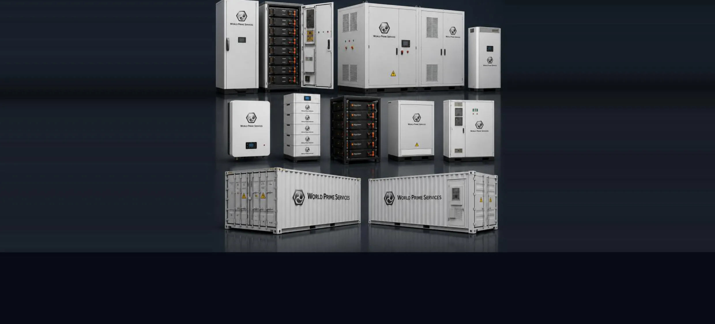
World Prime Services is an international engineering, consulting, commercial representation and global supply company focused on Battery Energy Storage Systems (BESS), power conversion, grid integration and related electrical infrastructure. We support clients from the first technical discussion through supplier selection, engineering coordination, factory inspection, export, commissioning and after-sales support.
Through strategic partnerships with top manufacturers, strict quality assurance and global logistics via Hong Kong, we ensure our clients around the world receive safe, efficient and long-lasting energy storage systems.

We act as the client's technical and commercial interface, translating project requirements into a coordinated equipment package, procurement strategy and delivery plan.
Solutions are sourced from selected Chinese manufacturers and technology partners and coordinated for international export, including commercial operations through Hong Kong when applicable.
Our value is built around multidisciplinary project coordination. The World Prime Services model combines energy engineering, industrial sourcing, international trade, logistics and client-side project management. This allows customers to evaluate several qualified technologies through one coordinated commercial channel while maintaining clear technical requirements, documentation control and accountability.
| Project Stage | World Prime Services Contribution |
|---|---|
| Opportunity definition | Load profile review, project objectives, operating mode and preliminary solution concept |
| Technical development | Energy and power sizing, system architecture, supplier requirements and interface definition |
| Commercial procurement | Factory comparison, scope alignment, exclusions review and contract support |
| Production and inspection | Document review, quality plan, FAT coordination and pre-shipment verification |
| Delivery and operation | Export coordination, commissioning planning, training, warranty and lifecycle support |
World Prime Services provides practical engineering support to align the battery system with the electrical network, operating profile, site conditions and commercial objectives. The scope can range from preliminary advisory work to full technical coordination of a turnkey BESS package.

| Engineering Service | Typical Deliverable |
|---|---|
| Feasibility and load analysis | Demand profile, use-case definition, energy/power ratio and operating strategy |
| System sizing | MW/MWh rating, duration, cycle profile, reserve margin and augmentation concept |
| Electrical integration | Single-line concept, PCS selection, transformer/MV interface and protection philosophy |
| Controls integration | BMS, EMS, SCADA, metering, communications and remote monitoring requirements |
| Site and installation | Footprint, access, clearances, auxiliaries, environmental limits and installation concept |
| Commercial and lifecycle review | CAPEX scope, OPEX factors, warranties, availability and degradation assumptions |
World Prime Services represents and cooperates with selected reputable and large Chinese manufacturers of battery cells, modules, racks, outdoor cabinets, liquid-cooled systems, containerized BESS, power conversion equipment and medium-voltage packages. Partner selection is based on product maturity, manufacturing capability, quality systems, test documentation, customization capacity and international project support.
The recommended configuration is selected against the customer's operating requirements rather than a single fixed product. This gives the project access to different cell platforms, PCS technologies, cooling methods, enclosure formats and control architectures while preserving one coordinated technical and commercial interface.
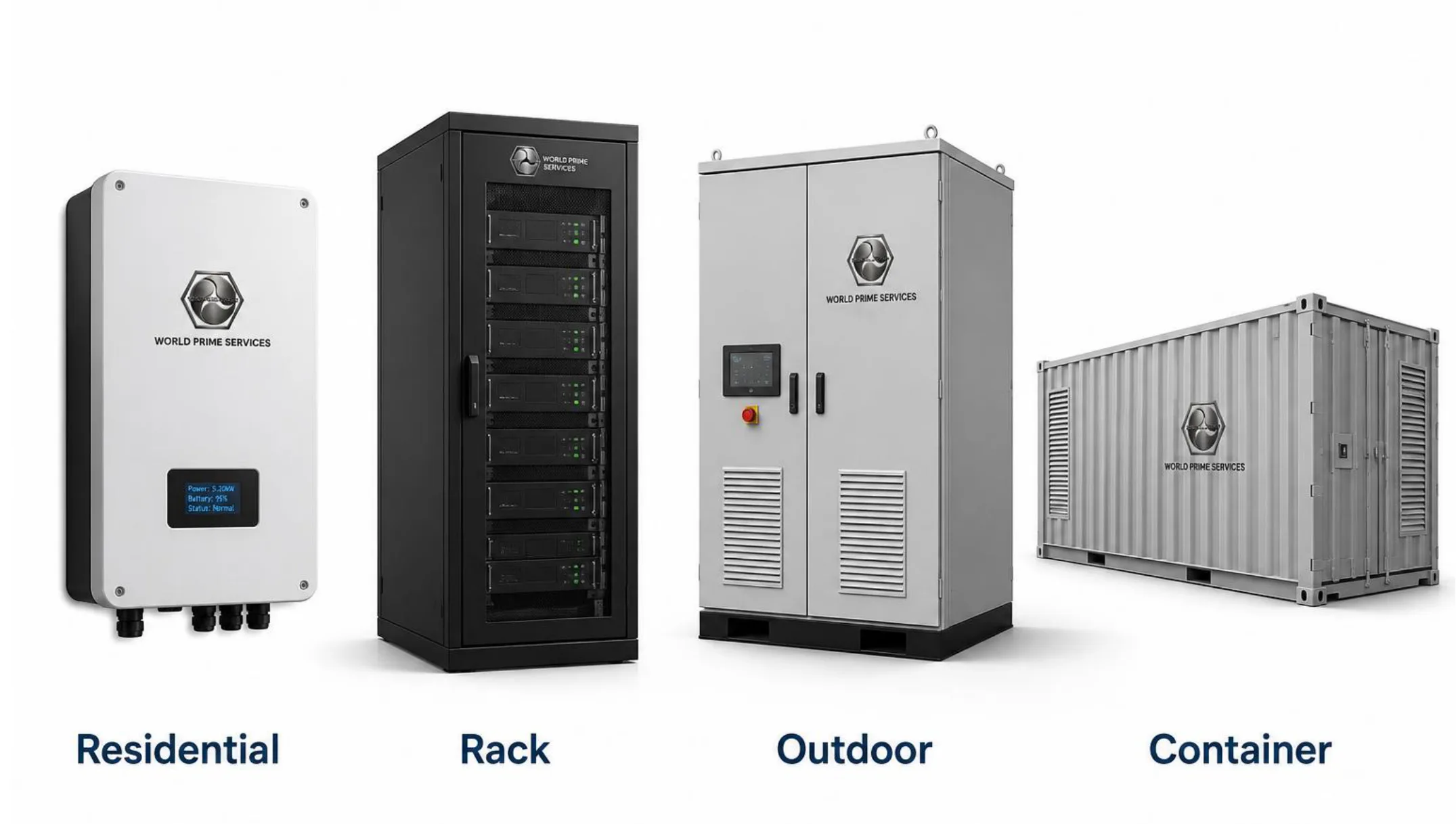
| Product Family | Typical Range | Primary Applications |
|---|---|---|
| Residential ESS | 5–20 kWh por unidade | Solar self-consumption, backup and time-of-use optimization |
| High-Voltage Rack ESS | 50–300 kWh | Commercial facilities, telecom, UPS and indoor BESS rooms |
| Outdoor Air-Cooled Cabinet | 100–500 kWh | Peak shaving, backup, microgrids and renewable integration |
| Outdoor Liquid-Cooled Cabinet | 215 kWh–1 MWh | High-cycle C&I, data centers and high-density sites |
| Containerized DC Block | 2-6.25 MWh class | Utility-scale storage, renewable plants and large microgrids |
| Integrated AC / MV Block | Project-specific MW/MWh | Turnkey grid-connected and grid-forming projects |
| PCS and Control Systems | 50 kW a multi-MW | Bidirectional conversion, dispatch and plant control |
Most stationary solutions are based on lithium iron phosphate (LiFePO4) chemistry due to its combination of thermal stability, cycle capability and suitability for daily energy-storage duty. Final cell selection depends on the required power, duration, temperature range, cycle profile, warranty and project certification strategy.
| System Layer | Function |
|---|---|
| Cell and module | Electrochemical energy storage, monitoring points and mechanical containment |
| Rack or battery cluster | Series/parallel configuration, local BMS, DC protection and service isolation |
| Battery system controller | State estimation, alarms, interlocks, balancing and coordination with PCS/EMS |
| PCS | Bidirectional AC/DC conversion, active/reactive power control and grid functions |
| EMS / SCADA | Dispatch, optimization, site control, historian, alarms and remote access |
| Thermal and fire systems | Temperature management, detection, ventilation, suppression and emergency response |
| Transformer / MV interface | Voltage transformation, protection, metering and grid connection |
Compact residential systems are designed for solar self-consumption, backup power and time-of-use management. Wall-mounted and floor-standing formats can be supplied with low-voltage or high-voltage architectures, compatible communications and modular expansion options.

| Model Series | Nominal Energy | Architecture | Typical Features |
|---|---|---|---|
| WPS-R5 | 5 kWh | Low-voltage | Compact wall/floor unit, smart BMS, local status |
| WPS-R10 | 10 kWh | Low or high voltage | Hybrid inverter compatibility and expandable capacity |
| WPS-R15 | 15 kWh | Modular | Parallel expansion and higher backup autonomy |
| WPS-R20 | 20 kWh | Modular | Large-home and small-commercial duty |
Final voltage, dimensions, usable energy, IP rating, communications and warranty are confirmed for the selected partner platform and destination market.
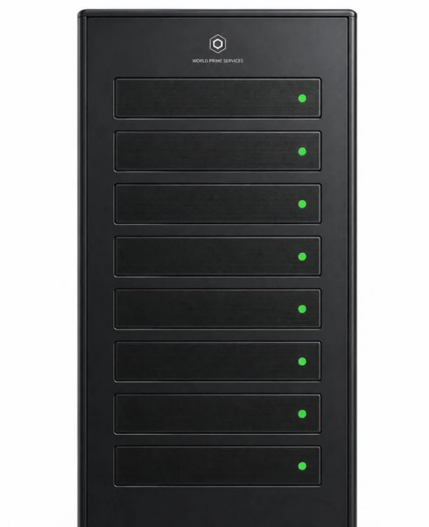
High-voltage rack systems provide modular energy capacity for indoor commercial, telecom, UPS and industrial applications. They are configured as one or more battery racks connected to a compatible PCS and coordinated through rack-level and system-level battery management.
| Series | Energy Class | Configuration | Application |
|---|---|---|---|
| WPS-RACK-50 | 50 kWh | Single compact rack | Telecom and small commercial |
| WPS-RACK-100 | 100 kWh | High-voltage rack | Commercial and UPS support |
| WPS-RACK-200 | 200 kWh | Multi-rack system | Industrial demand management |
| WPS-RACK-300 | 300 kWh | Multi-rack system | Microgrid and hybrid generation |
Typical integration includes rack-level BMS, master controller, DC protection, CAN/RS485/Ethernet communications and scalable parallel rack configuration.
Outdoor cabinets combine battery racks, controls, thermal management and safety systems in a weather-protected enclosure. Solutions may be supplied as DC battery cabinets or as integrated AC systems with PCS and distribution equipment.

| Series | Energy Class | Typical Power Class | Cooling |
|---|---|---|---|
| WPS-C100 | 100 kWh | 50–100 kW | Air cooled |
| WPS-C215 | 215 kWh | 100–125 kW | Air or liquid |
| WPS-C233 | 233 kWh | 100–125 kW | Air or liquid |
| WPS-C261 | 261 kWh | 125 kW | Liquid option |
| WPS-C372 | 372 kWh | 186–250 kW | Liquid cooled |
| WPS-C418 | 418 kWh | 200–250 kW | Liquid cooled |
| WPS-C500 | 500 kWh | 250 kW | Liquid cooled |
| WPS-C1000 | 1 MWh class | 500 kW class | Integrated outdoor system |
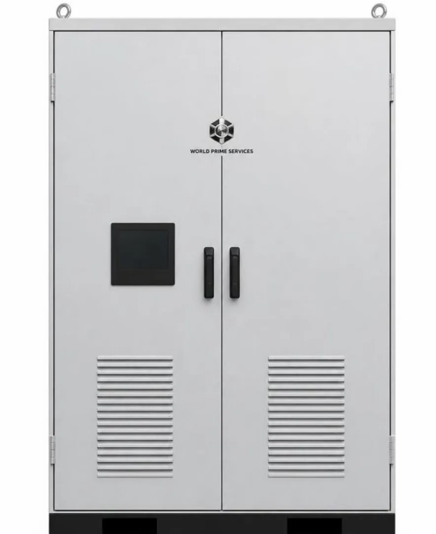
Liquid-cooled systems are intended for high-utilization and high-energy-density applications where tighter temperature control is required. The cooling circuit reduces cell-to-cell temperature variation and supports stable operation under demanding ambient and cycling conditions.
| Configuration | Typical Range | Key Characteristics |
|---|---|---|
| C&I liquid-cooled cabinet | 215–500 kWh | Compact footprint, high cycle duty and integrated safety systems |
| Large outdoor cabinet | 500 kWh–1 MWh | Higher energy density and centralized thermal management |
| Integrated AC block | 1-5 MWh class | Battery, PCS, controls and auxiliary systems in coordinated package |
| Grid-forming package | Project-specific | Weak-grid operation, renewable support and microgrid functionality |
Standard subsystems include battery racks, high-voltage box, liquid cooling unit, BMS, HMI/gateway, fire detection and suppression, gas detection, emergency ventilation and EMS/SCADA interface.
Containerized systems provide scalable multi-MWh building blocks for renewable energy plants, utilities, mining, data centers and large microgrids. Projects can use separate DC battery containers with centralized PCS stations or integrated AC blocks with conversion and medium-voltage interfaces.
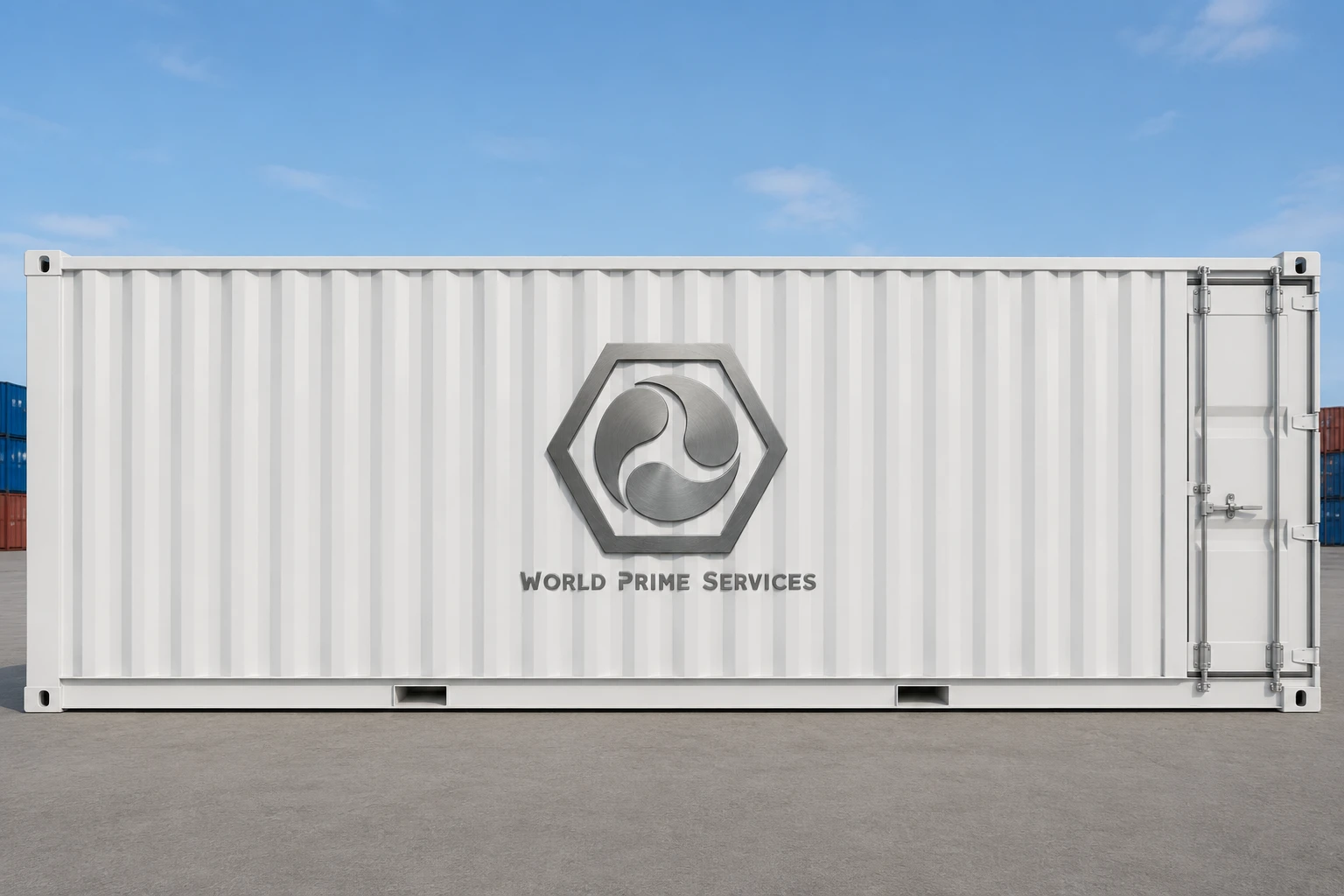
| Model Class | Nominal Energy | Format | Typical Use |
|---|---|---|---|
| WPS-2M | 2 MWh class | 20-ft class | Commercial and utility projects |
| WPS-3M | 3 MWh class | 20-ft class | Renewable shifting and grid services |
| WPS-3.44M | 3.44 MWh class | 20-ft high-density | Utility-scale DC block |
| WPS-5M | 5 MWh class | 20-ft liquid cooled | High-density utility projects |
| WPS-6.25M | 6.25 MWh class | High-density block | Large renewable and grid projects |
Energy, dimensions and transport configuration are selected according to cell platform, cooling design, certification scope, shipping restrictions and project duty cycle.
A bankable BESS requires coordinated subsystems, clear responsibility boundaries and tested communications. World Prime Services can coordinate the battery platform with power conversion, controls, transformers, switchgear, protection, metering and plant-level supervision.
| Subsystem | Scope Options | Main Function |
|---|---|---|
| Bidirectional PCS | String or centralized; indoor or outdoor | Active/reactive power conversion, grid support and islanding functions |
| Battery Management System | Module, rack and system levels | Monitoring, state estimation, balancing, protection and interlocks |
| Energy Management System | Local controller or plant controller | Scheduling, optimization, SOC management and asset coordination |
| SCADA and communications | HMI, historian, gateway and remote access | Alarms, trends, reports, cybersecurity interfaces and dispatch integration |
| Transformer and MV station | Dry-type or oil-filled; skid or container | Voltage transformation, protection, metering and grid interconnection |
| Auxiliary systems | UPS, HVAC, fire system and lighting | Safe and reliable operation of the complete installation |
| Application | BESS Value |
|---|---|
| Peak shaving and demand management | Reduces maximum demand and manages contracted capacity |
| Renewable energy shifting | Stores solar or wind generation for later delivery |
| Backup and resilience | Maintains critical loads during grid disturbances or outages |
| Microgrid operation | Coordinates grid, renewable generation, diesel and battery resources |
| Data centers | Supports reliability, ramp management and integration with UPS/generation |
| Mining and industry | Reduces fuel consumption, stabilizes weak grids and manages large loads |
| EV charging hubs | Limits grid demand and supports high-power charging |
| Grid services | Provides frequency response, voltage support, reserve and capacity services |
A structured delivery process reduces technical gaps between the battery supplier, PCS supplier, EPC contractor, grid operator and end user. World Prime Services adapts the level of support to the project stage and contract structure.
| Phase | Key Activities |
|---|---|
| 1. Definition | Objectives, load profile, site conditions, grid parameters, duration and operating strategy |
| 2. Concept engineering | Sizing, architecture, equipment options, footprint and preliminary interfaces |
| 3. Technical procurement | Specification, partner selection, bid normalization and scope clarification |
| 4. Detailed coordination | Drawings, data sheets, communications, protection, auxiliaries and documentation register |
| 5. Manufacturing and FAT | Production follow-up, inspection plan, FAT procedure and punch-list closure |
| 6. Export and delivery | Packing, shipping documents, logistics coordination and receiving requirements |
| 7. Installation and commissioning | Site readiness, SAT support, energization, functional tests and training |
| 8. Lifecycle support | Remote support, preventive maintenance, spare parts and warranty coordination |
Quality assurance is managed against the approved technical specification and project documentation list. Inspection scope is agreed before production and can include remote reviews, on-site factory visits and independent third-party inspection.
| Document Group | Typical Content |
|---|---|
| Technical | Data sheets, drawings, single-line diagrams, architecture and interface lists |
| Quality | Inspection plan, test procedures, FAT records and non-conformance closure |
| Compliance | Certificates, declarations, battery transport test summary and safety documents |
| Operation | Installation manual, commissioning procedure, O&M manual and spare-parts list |
World Prime Services coordinates international trade and export activities for BESS equipment manufactured in China, including commercial routing through Hong Kong where appropriate. The logistics plan is developed around battery classification, container dimensions, destination requirements, Incoterms and project schedule.
| Workstream | Support Scope |
|---|---|
| Commercial and export documents | Quotation, commercial invoice, packing list, certificate support and contractual document coordination |
| Battery transport documentation | UN 38.3 test summary and applicable dangerous-goods documentation from the selected manufacturer |
| Packing and handling | Export packing, lifting points, moisture protection, shock indicators and handling instructions |
| Ocean and multimodal transport | Container planning, port coordination, freight forwarding and delivery interfaces |
| Destination preparation | Import-document support, unloading plan, storage conditions and site receiving checklist |
Technical support continues beyond shipment. Depending on project scope and destination, support can be provided remotely or on site in coordination with the selected manufacturer, local EPC contractor and service partners.
| Service | Typical Scope |
|---|---|
| Installation review | Site readiness, equipment placement, cable routing, auxiliaries and pre-energization checks |
| Commissioning support | BMS/PCS/EMS configuration, communications, functional tests and operating-mode verification |
| Performance verification | Capacity, power, efficiency, alarms, dispatch and interface checks |
| Training | Operator training, emergency procedures, routine inspection and basic troubleshooting |
| O&M support | Preventive maintenance plan, remote diagnostics, software support and service coordination |
| Warranty coordination | Failure analysis, spare-parts processing, repair/replacement coordination and documentation |
Certification and compliance requirements depend on the destination country, installation type, authority having jurisdiction and project contract. The selected partner platform and complete system scope must be reviewed against the applicable codes before purchase.
| Reference Area | Typical Standards / Evidence |
|---|---|
| Industrial battery safety | IEC 62619 e/ou IEC 63056, conforme especificado |
| Stationary battery systems | UL 1973 where North American certification is required |
| Complete energy storage system | UL 9540 where specified |
| Thermal event assessment | UL 9540A test information where required by project or authority |
| Installation and fire code | NFPA 855 and local fire/building requirements where applicable |
| Lithium battery transport | UN Manual of Tests and Criteria, Section 38.3 documentation |
| Electrical integration | Applicable IEC, IEEE, utility and local grid-connection requirements |
The following matrix supports early-stage selection of a suitable World Prime Services BESS configuration. Final equipment, ratings, dimensions and certifications are confirmed after review of the load profile, grid connection, required operating duration, environmental conditions and destination-market requirements.
| Solution Family | Typical Energy Range | Power / Duration | Primary Configuration | Typical Use |
|---|---|---|---|---|
| Residential ESS | 5–40 kWh | 3–20 kW / 1–4 h | Low-voltage or high-voltage modular battery | Solar self-consumption, backup |
| High-Voltage Rack ESS | 50–500 kWh | 30–250 kW / 1–4 h | Indoor racks with external PCS | Commercial, telecom, UPS |
| Outdoor Cabinet ESS | 100 kWh–1 MWh | 50 kW–500 kW / 1–4 h | Integrated or DC battery cabinet | C&I, microgrid, EV charging |
| Liquid-Cooled ESS | 215 kWh–7+ MWh | 100 kW–3+ MW / 2–8 h | High-density liquid-cooled blocks | High utilization, data centers |
| Containerized ESS | 2-9+ MWh per unit | 1–5+ MW / 2–8 h | 20 ft / 40 ft DC or AC block | Utility, renewable plants, mining |
World Prime Services residential product family — full-product studio presentation
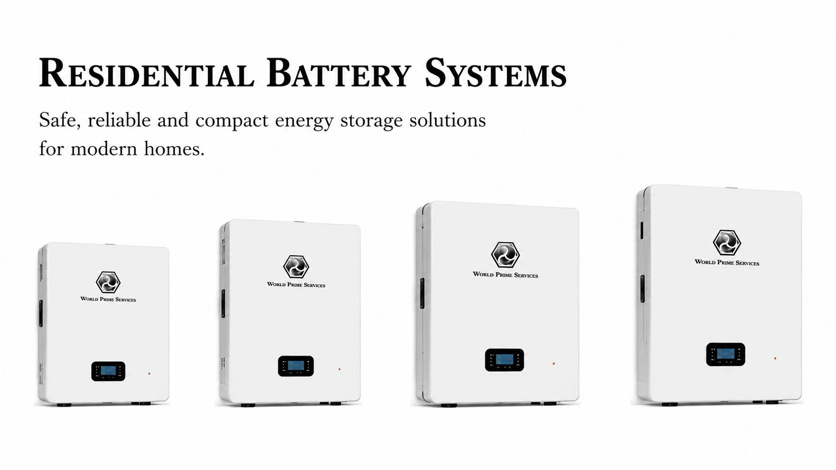
Residential and small commercial platforms are supplied in wall-mounted, floor-standing and modular stack configurations. LiFePO4 chemistry, intelligent BMS, inverter communications and configurable backup operation support solar self-consumption, time-of-use management and resilient power.
| Model Class | Nominal Energy | Voltage Platform | Scalability | Installation |
|---|---|---|---|---|
| WPS-R5 | 5 kWh | 48–51,2 V | Parallel expansion | Wall / floor |
| WPS-R10 | 10 kWh | 48-51.2 V or HV | Modular expansion | Wall / floor |
| WPS-R15 | 15 kWh | HV modular | Stack or parallel | Floor |
| WPS-R20 | 20 kWh | HV modular | Multi-module | Floor |
High-voltage racks and outdoor cabinets provide scalable building blocks for commercial and industrial projects. Systems may be supplied as battery-only DC equipment or as integrated AC solutions with PCS, EMS, auxiliary power, thermal management and fire protection.
| Series | Energy Class | Cooling | Protection | Integration |
|---|---|---|---|---|
| WPS-RACK | 50–500 kWh | Air / room HVAC | Indoor cabinet | External PCS |
| WPS-C100 | 100 kWh | Air cooled | IP54 / IP55 opcional | Battery or all-in-one |
| WPS-C215 / C233 | 215–233 kWh | Air or liquid | IP54 / IP55 | Integrated C&I |
| WPS-C372 / C418 | 372–418 kWh | Liquid option | IP55 | High-density C&I |
Utility and large industrial projects are configured as modular energy blocks. Current market platforms commonly combine high-density LFP batteries, liquid cooling, rack-level controls and either centralized PCS stations or integrated AC-block architecture. The selected configuration is optimized for duration, transport, site footprint, maintenance strategy and grid requirements.
| Platform | Energy Class | Typical Container | Cooling | Architecture |
|---|---|---|---|---|
| WPS-LC-215 | 215–261 kWh | Outdoor cabinet | Liquid cooled | C&I all-in-one |
| WPS-LC-500 | 372–500 kWh | Outdoor cabinet | Liquid cooled | DC / AC cabinet |
| WPS-CONT-2M | 2–3 MWh | 20-ft class | Liquid cooled | DC block |
| WPS-CONT-5M | 5–7+ MWh | 20-ft class | Liquid cooled | DC or AC block |
The power conversion and grid-connection package is selected as a coordinated electrical system. World Prime Services can align the battery operating window, PCS DC range, transformer ratio, switchgear ratings, protection philosophy, auxiliary supply and plant-controller interface.
| Subsystem | Typical Range | Key Selection Parameters | Optional Scope |
|---|---|---|---|
| Bidirectional PCS | 30 kW–5+ MW | DC voltage, overload, THD, efficiency, grid code | Grid-forming, black start |
| LV Transformer | 0,4–0,8 kV | PCS output, vector group, losses, impedance | Dry type / oil immersed |
| MV Transformer | 6-35 kV typical | Utility voltage, grounding, insulation level | Skid or container station |
| MV Switchgear / PPC | Project-specific | Protection, metering, dispatch and interlocks | RMU, metal-clad, plant control |
Packages can be quoted as battery-only, battery plus PCS, low-voltage AC block or medium-voltage block. Installation and local approval scope are defined in the project offer.
The control architecture coordinates the battery, PCS, auxiliary systems and site-level operating strategy. A clear hierarchy prevents conflicting commands and establishes responsibility for dispatch, protection, alarms, historical data and remote service access.
| Layer | Main Function | Typical Interfaces | Typical Data |
|---|---|---|---|
| Battery BMS | Cell and rack protection | CAN, RS485, Ethernet | Voltage, temperature, SOC, SOH |
| System Controller | Cabinet / container coordination | Modbus TCP, IEC protocols | Limits, alarms, availability |
| EMS | Economic and operational dispatch | Modbus, OPC UA, API | Schedules, setpoints, forecasts |
| SCADA | Plant supervision and historian | IEC 61850, IEC 60870-5-104, DNP3 | Events, trends, reports |
Accurate project data allows the engineering team and selected manufacturing partners to provide a technically aligned quotation, avoid unnecessary oversizing and identify local compliance requirements before production.
| Information Group | Required Input |
|---|---|
| Site and Country | Installation address, altitude, ambient temperature, humidity, corrosion category and seismic data |
| Electrical Network | Grid voltage, frequency, short-circuit level, grounding method, point of connection and grid-code requirements |
| Operating Profile | 15-minute or hourly load data, peak demand, renewable generation profile and critical loads |
| Performance | Required power, usable energy, duration, cycles per day, SOC window, response time and availability |
| Commercial / Compliance | Delivery term, schedule, warranty, installation scope, certification, fire code and utility requirements |
Where complete information is not yet available, World Prime Services can prepare a preliminary concept and list the assumptions that must be validated before final equipment selection.
World Prime Services structures the commercial offer around the customer's preferred contracting model. The proposal identifies the included equipment, engineering deliverables, tests, documentation, logistics, field services, warranty responsibilities and exclusions.
| Scope Module | Base Supply | Optional Services |
|---|---|---|
| Equipment | Battery system and agreed accessories | PCS, transformer, MV station, spares |
| Engineering | Technical coordination and approved data sheets | Studies, detailed design review, interface management |
| Quality | Routine tests and supplier documentation | Factory audit, third-party inspection, witnessed FAT |
| Logistics | Export packing and commercial documents | Freight, insurance, customs support, site delivery |
| Site Services | Remote technical support | Installation supervision, SAT, commissioning, training |
All technical values in this continuation are reference classes for project development. Binding ratings, dimensions, certification status, delivery schedule, warranty and commercial terms are established only in the project-specific quotation and approved contract documents.
Every BESS project begins with a documented design basis that converts commercial objectives into measurable technical requirements. World Prime Services coordinates customer data, utility requirements and selected manufacturing platforms to establish the operating envelope before equipment is released for production.
| Design Area | Minimum Definition | Engineering Output |
|---|---|---|
| Duty and Use Case | Operating mode, dispatch objective, cycles per day, response time | Functional requirements and control philosophy |
| Power and Energy | Rated power, usable energy, duration, overload and auxiliary demand | Battery and PCS configuration |
| Site Conditions | Temperature, altitude, humidity, corrosion, dust, seismic and access | Enclosure, cooling and derating basis |
| Grid Interface | Voltage, frequency, short-circuit level, grounding and utility rules | Transformer, switchgear and protection concept |
| Commercial Requirements | Schedule, warranty, availability, logistics and service scope | Project execution and supply responsibility matrix |
Changes after design freeze are managed through a formal technical and commercial change process to protect schedule, quality and system compatibility.
System sizing is based on usable delivered energy rather than nameplate capacity alone. The engineering calculation considers depth of discharge, conversion losses, auxiliary consumption, temperature effects, degradation, operating reserve and the required performance at the defined warranty point.
| Sizing Element | Engineering Consideration | Typical Result |
|---|---|---|
| Load Requirement | Critical load, peak demand or dispatch setpoint | Required AC power |
| Discharge Duration | Energy required at the point of connection | Usable AC energy |
| Efficiency Chain | Battery, PCS, transformer and cable losses | DC energy requirement |
| Operating Window | SOC limits, reserve and emergency margin | Installed energy capacity |
| Degradation Allowance | Calendar aging, cycling and temperature | Beginning-of-life oversizing |
| Availability Strategy | Redundancy, maintenance blocks and spare capacity | Number of parallel blocks |
Final values are confirmed in the project-specific technical agreement and manufacturer performance guarantee. Reference catalog values do not replace the approved project calculation.
The electrical architecture is selected to match project scale, maintainability and the point-of-connection requirements. The solution may be configured as a DC battery block, an integrated low-voltage AC block or a complete medium-voltage power station.
| Configuration | Main Characteristics | Typical Application |
|---|---|---|
| DC-Coupled | Battery connected to a common DC bus with renewable generation | Solar plus storage and optimized DC utilization |
| AC-Coupled | Independent battery PCS connected to the AC system | Retrofit, grid services and flexible operation |
| Centralized PCS | Large power blocks with shared conversion equipment | Utility-scale and high-power applications |
| Integrated MV Block | Battery, PCS, transformer and switchgear coordinated as one package | Fast site deployment and standardized plants |
Safety is implemented through independent layers that detect abnormal conditions, limit propagation and place the system in a controlled state. The final protection philosophy is coordinated with the selected battery, PCS, fire system, switchgear and local emergency-response requirements.
| Protection Layer | Examples of Functions | Typical Action |
|---|---|---|
| Cell / Module | Voltage, temperature and current supervision | Alarm, current limit or module isolation |
| Rack / Battery System | Insulation monitoring, contactor control, fuse and HV interlock | Rack shutdown and DC isolation |
| PCS / AC System | Overcurrent, over/undervoltage, frequency and anti-islanding | Converter trip and AC isolation |
| Thermal / Gas Detection | Smoke, heat, off-gas and cooling-system monitoring | Alarm, ventilation response and shutdown |
| Site Protection | Transformer differential, feeder protection, arc and earth-fault functions | Selective plant isolation |
Design and verification may reference IEC 62619, IEC 62933-5-1, IEC 62933-5-2, UL 9540, UL 9540A, NFPA 855, IEEE 1547 and applicable local requirements. The binding compliance list is project-specific.
Thermal management maintains cell temperature within the operating range and reduces temperature variation across the battery population. The cooling design is selected according to power density, ambient conditions, duty cycle, serviceability and project life requirements.
| System | Air Cooling | Liquid Cooling |
|---|---|---|
| Typical Application | Lower-density indoor or outdoor cabinets | High-density cabinets and containers |
| Heat Removal | Forced-air circulation and HVAC | Coolant loop, cold plates and chiller |
| Temperature Uniformity | Dependent on airflow path and filter condition | More controlled rack and cell temperature distribution |
| Maintenance Focus | Filters, fans, coils and airflow obstruction | Pumps, coolant quality, leak detection and heat exchanger |
Fire protection is engineered with enclosure volume, ventilation, detection, battery chemistry, test evidence and local emergency requirements.
Quality assurance begins before assembly through supplier qualification, approved drawings, component traceability and inspection planning. World Prime Services can coordinate factory surveillance and witnessed testing according to the agreed inspection and test plan.
| Inspection Stage | Representative Checks | Documented Record |
|---|---|---|
| Incoming Materials | Cell/module identification, certificates, enclosure and electrical components | Receiving inspection and traceability records |
| Assembly | Torque, wiring, polarity, insulation, cooling and labeling | Production checklist and nonconformance log |
| Functional Test | BMS communication, alarms, interlocks, contactors, HVAC and emergency stop | Factory functional-test report |
| Electrical Test | Insulation resistance, dielectric tests where applicable and protection checks | Electrical test certificate |
| Integrated FAT | Charging/discharging, PCS control, EMS interface and simulated faults | Approved FAT protocol and signed report |
Site execution is coordinated through defined installation prerequisites and hold points. Equipment energization begins only after civil, mechanical, electrical, communication and safety checks have been completed and accepted.
| Phase | Principal Activities | Acceptance Evidence |
|---|---|---|
| Pre-Installation | Foundation, access, lifting plan, grounding, cable routes and auxiliary supply | Site-readiness checklist |
| Electrical Installation | DC/AC/MV terminations, torque, polarity, grounding and insulation checks | Electrical completion certificate |
| Communication | BMS, PCS, EMS, SCADA, time synchronization and remote-access validation | Point-to-point and communication report |
| SAT | Interlocks, alarms, protection, emergency stop and operating sequences | Signed SAT protocol |
| Commissioning | Controlled energization, charge/discharge test and dispatch verification | Commissioning and performance report |
Local contractors, utility representatives and authorities remain responsible for activities assigned by law, permit or contract. Service boundaries are stated in the project offer.
Lifecycle performance depends on controlled operation, environmental management, software discipline and preventive maintenance. World Prime Services can coordinate remote support, spare parts, technical service and manufacturer escalation throughout the agreed warranty period.
| Service Area | Routine Scope | Lifecycle Objective |
|---|---|---|
| Remote Monitoring | SOC, SOH, alarms, temperatures, availability and event review | Early detection and operating optimization |
| Preventive Maintenance | Visual inspection, filters, cooling system, torque, protection and emergency devices | Reduce unplanned outages |
| Battery Health | Capacity trends, imbalance, resistance and degradation review | Maintain usable energy and detect abnormal aging |
| Software and Controls | Approved firmware, backups, user access and parameter governance | Stable and secure operation |
| Spare Parts | Critical spares, consumables and replacement-module strategy | Shorten recovery time |
Lifecycle planning may include augmentation, repowering, module replacement and compliant recycling. Responsibilities are defined by local requirements and the supply contract.
The technical value of a BESS depends on matching the equipment configuration, control strategy and commercial objective to the actual operating profile. World Prime Services develops the application basis from measured load data, generation forecasts, tariff structure, grid restrictions and required resilience level.
| Application Objective | Principal Engineering Inputs | Typical Design Output |
|---|---|---|
| Peak Shaving | Interval demand profile, demand tariff, maximum import limit | PCS power, usable energy and dispatch threshold |
| Energy Arbitrage | Time-of-use prices, cycling window and efficiency boundary | Charge/discharge schedule and economic cycle limit |
| Backup Power | Critical-load list, autonomy time and transfer philosophy | Island capacity, reserve SOC and switchgear concept |
| Renewable Integration | Solar/wind profile, curtailment and interconnection limits | Firming, ramp control and export-limitation logic |
| Grid Services | Response time, accuracy, telemetry and market rules | Control functions, reserve allocation and compliance test plan |
Energy storage improves the controllability of variable renewable generation by shifting energy, limiting export, smoothing ramps and supporting dispatch commitments. The final architecture may be AC-coupled, DC-coupled or configured as a hybrid power station with plant-level control.
| Renewable Application | BESS Function | Key Integration Requirement |
|---|---|---|
| Solar Energy Shifting | Store midday production and discharge during higher-value periods | Forecasting, clipping analysis and charge-window control |
| Solar Export Limitation | Maintain grid export below a contractual threshold | Fast plant controller and reliable point-of-connection metering |
| Wind Smoothing | Reduce rapid power variation and improve scheduled output | High-response PCS and coordinated turbine/BESS dispatch |
| Curtailment Recovery | Capture energy that would otherwise be curtailed | Available charging headroom and grid-code compliance |
| Hybrid Renewable Plant | Coordinate solar, wind, storage and auxiliary generation | Unified EMS/PPC, common telemetry and operating-priority matrix |
Commercial and industrial facilities require solutions that combine energy-cost reduction with operational continuity. The BESS is engineered around load criticality, power quality, available short-circuit level, site conditions and the customer's operating procedures.
| Sector | Typical Requirements | Representative BESS Scope |
|---|---|---|
| Manufacturing | Demand reduction, process continuity and renewable self-consumption | Outdoor cabinet or container BESS with facility EMS |
| Mining | Remote operation, diesel reduction, harsh environment and large motor loads | Ruggedized container BESS, microgrid controller and MV integration |
| Data Centers | Fast response, high availability, redundancy and controlled backup support | Modular BESS blocks, redundant controls and critical-load interface |
| Ports and Logistics | Peak demand, electrified equipment and charging coordination | High-power PCS, schedule optimization and load management |
| Commercial Buildings | Tariff optimization, solar integration and emergency loads | Compact C&I BESS with remote monitoring and building interface |
A microgrid BESS must manage transitions between grid-connected and islanded operation while maintaining stable voltage and frequency. The system design coordinates the PCS, generator controls, renewable sources, protection relays, transfer equipment and critical-load priorities.
| Operating Mode | Control Objective | Engineering Considerations |
|---|---|---|
| Grid-Connected | Optimize energy cost and provide grid support | Import/export limits, tariff logic and utility commands |
| Transition to Island | Maintain continuity or execute controlled transfer | Protection coordination, transfer time and load shedding |
| Island Operation | Balance generation, storage and demand | Grid-forming capability, spinning reserve and SOC management |
| Black Start | Energize the microgrid without an external source | Auxiliary supply, transformer energization and staged load pickup |
| Grid Resynchronization | Return to utility operation without disturbance | Synchronism check, ramp control and transfer sequence |
A technically correct BESS proposal must also define the commercial assumptions that influence lifecycle value. World Prime Services structures the evaluation around project duty, electricity economics, degradation, availability, maintenance and the selected supply boundary.
| Evaluation Input | Required Information | Commercial Effect |
|---|---|---|
| Energy Tariff | Demand charges, time-of-use prices and escalation assumptions | Revenue and savings profile |
| Operating Duty | Cycles per day, depth of discharge and standby periods | Battery throughput and degradation |
| Project Life | Evaluation period, replacement strategy and residual value | Lifecycle cost and augmentation planning |
| Availability | Planned maintenance and unplanned outage assumptions | Guaranteed service level and lost-value exposure |
| Supply Boundary | Equipment, installation, grid works, taxes and logistics | CAPEX comparison and responsibility allocation |
The proposal process converts the approved technical basis into a controlled commercial offer. Each quotation identifies scope, exclusions, interfaces, schedule, documentation, warranty conditions and acceptance criteria to reduce ambiguity during execution.
| Commercial Document | Principal Content | Purpose |
|---|---|---|
| Technical Proposal | Configuration, performance, drawings, controls and compliance | Defines the offered solution |
| Scope Matrix | Supply, installation, civil works, grid connection and customer responsibilities | Clarifies interfaces and exclusions |
| Commercial Offer | Pricing, validity, payment terms, Incoterm and taxes | Establishes commercial conditions |
| Project Schedule | Design approvals, production, FAT, shipment, installation and SAT | Creates delivery milestones |
| Contract Annexes | Warranty, liquidated damages, acceptance and change management | Allocates contractual risk |
Lifecycle support begins with a clearly defined warranty boundary and service plan. Warranty terms are aligned with the selected manufacturer platform, operating duty, environmental conditions, maintenance obligations and the agreed performance reference point.
| Support Element | Typical Scope | Customer Benefit |
|---|---|---|
| Product Warranty | Defects in materials and workmanship under agreed conditions | Corrective support and replacement process |
| Performance Warranty | Capacity retention, efficiency or availability where contracted | Measurable long-term performance commitment |
| Spare Parts Package | Critical electronic, cooling, protection and communication components | Reduced repair time and inventory planning |
| Remote Support | Alarm review, diagnostics, software support and operating guidance | Faster troubleshooting and optimized operation |
| Field Service | Inspection, repair, preventive maintenance and technical supervision | Local restoration and lifecycle reliability |
Complete project information enables faster selection, accurate pricing and a technically compliant proposal. The following checklist should be completed before final equipment configuration and commercial submission.
| Information Category | Minimum Customer Data | Example / Format |
|---|---|---|
| Project Location | Country, site coordinates, altitude and environmental conditions | Site data sheet |
| Power and Energy | Rated MW, usable MWh, duration, overload and reserve requirement | Operating specification |
| Operating Profile | Load/generation data, cycles, SOC limits and dispatch objective | 12-month interval data |
| Grid Interface | Voltage, frequency, fault level, grounding and utility rules | Single-line diagram and grid code |
| Site and Logistics | Layout, access, lifting limits, foundations and delivery restrictions | Site drawings and logistics survey |
| Commercial Requirements | Delivery date, Incoterm, warranty, financing and local scope | Request for quotation |